
Intermediate Distribution Frame (IDF): Complete Guide
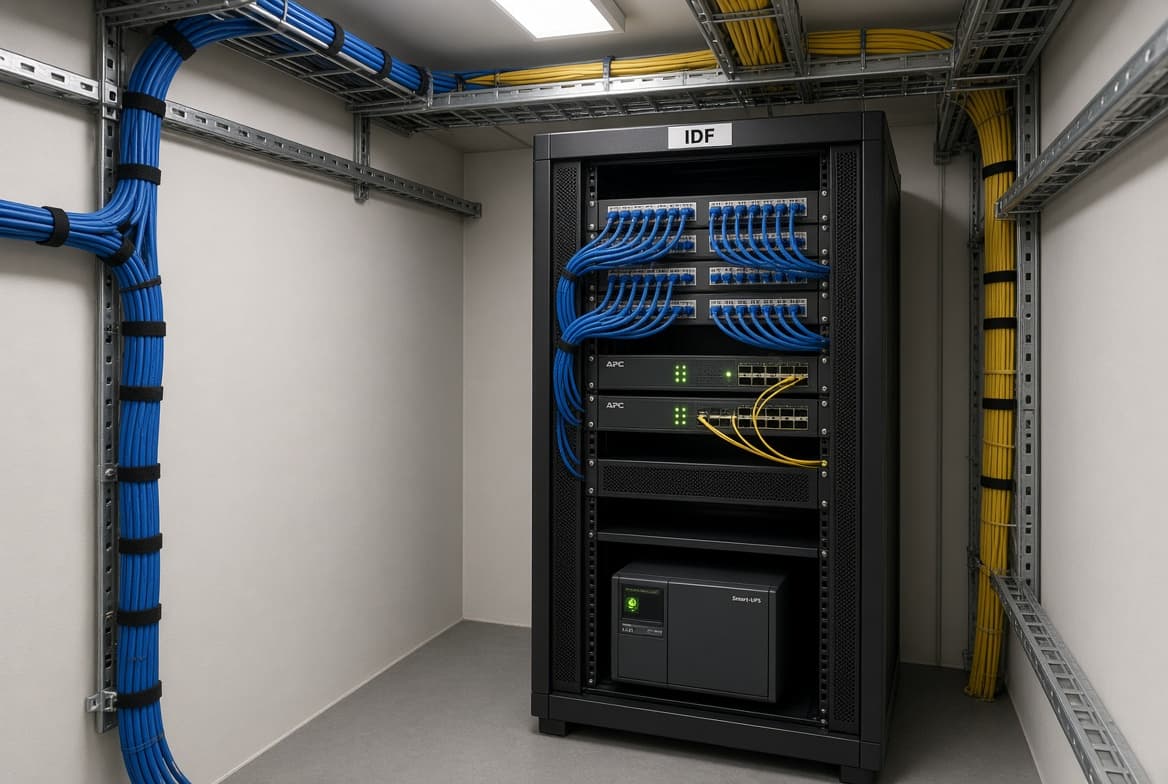
An intermediate distribution frame (IDF) is a telecommunications room, closet, or distribution location that connects a building’s horizontal cabling to its main distribution frame (MDF). It commonly contains patch panels, access switches, fiber connections, and supporting power equipment.
In a traditional office, school, hospital, or multi-story building, an IDF serves a defined floor or coverage area. If its switches, power, or backbone connection fail, the users and devices connected through that location may lose network, voice, or wireless service.
Technically, an IDF provides an intermediate connection point between the building’s main distribution area and the horizontal cabling that serves users and devices. It may connect patch panels, access switches, fiber uplinks, wireless access points, IP phones, computers, cameras, and other network endpoints back to the MDF through backbone cabling.
Table of Contents
Where an IDF Sits in the Cabling Hierarchy
Structured cabling commonly separates the main distribution area, intermediate distribution locations, and user work areas. In a traditional design, the MDF or main equipment room connects to IDFs through backbone cabling, while IDFs connect to workstations, phones, wireless access points, cameras, and other endpoints through horizontal cabling.
Cable distance is one of the main reasons designers use multiple IDFs, but it is not the only factor. Floor layout, pathway capacity, backbone design, equipment density, power, cooling, security, and future expansion also influence closet placement.
For balanced twisted-pair copper cabling, structured-cabling designs commonly use a 90-meter maximum permanent-link length, with additional allowance for patch cords and equipment cords within the complete channel. The practical distance between an IDF and a wall outlet therefore depends on the route, patching arrangement, and the cabling design, not simply the straight-line distance between two rooms.
The commonly discussed 100-meter channel allowance includes the permanent link plus patch cords and equipment cords. The 90-meter figure should therefore not be interpreted as a universal straight-line distance from the IDF room to a workstation.
This distance limit is one reason large buildings use multiple IDFs. If horizontal cable routes would exceed the permitted channel length, designers may add another telecommunications room, change the closet location, or use a different backbone and edge architecture.
| Tier / Area | Common Name | Main Function | Typical Equipment |
|---|---|---|---|
| Main distribution | MDF / Main Equipment Room | Building entry, backbone, and core distribution | Core switches, routers, firewalls, carrier demarcation, fiber panels |
| Intermediate distribution | IDF / Telecommunications Room | Serves a floor, zone, or coverage area | Patch panels, access switches, fiber panels, UPS |
| User edge | Work Area | Connects users and endpoint devices | Wall outlets, computers, IP phones, cameras, access points |
Terminology varies by project and standard. Some documents use MDF and IDF, while others use terms such as main cross-connect, intermediate cross-connect, telecommunications room, or distributor room.
Example: How an IDF Serves an Office Floor
Imagine a three-story office building with a main equipment room in the basement. The MDF contains the core switches, firewall, carrier connection, and building backbone connections.
In this example, each floor has an IDF containing access switches and patch panels. Ethernet cables run from the floor’s IDF to desks, IP phones, printers, cameras, and wireless access points. Fiber uplinks connect each IDF back to the MDF.
If the second-floor IDF loses power, users connected through that closet may lose wired and wireless service. The first and third floors may continue operating if their IDFs and backbone connections remain available.
IDF vs. MDF: What Actually Separates Them
The MDF and IDF have different roles in a traditional structured-cabling design. The MDF is usually the primary telecommunications or equipment location where external service-provider connections, backbone cabling, and core network equipment are concentrated. An IDF is a secondary distribution location that serves a floor, zone, or group of endpoints and connects back to the MDF through backbone cabling.
The MDF usually has a larger potential impact because it may contain core equipment and major backbone connections. An IDF outage is more likely to affect the floor, zone, or endpoint group served by that location. The actual impact depends on network redundancy, switch placement, fiber paths, wireless design, and whether critical services have alternate connections.
Some environments also use the term combined distribution frame (CDF) for a location or frame that combines functions normally separated between distribution points. The terminology is not universal, so the project’s drawings and cabling specifications should define what MDF, IDF, and CDF mean in that environment.
| Attribute | MDF | IDF |
|---|---|---|
| Typical location | Main equipment or telecommunications room | Telecommunications room, closet, or cabinet serving a zone |
| Main connection | Service-provider entry, core network, and backbone | Horizontal cabling, local switches, and backbone connection to MDF |
| Typical equipment | Core switches, routers, firewalls, carrier demarcation, fiber panels | Patch panels, access switches, fiber panels, UPS |
| Typical impact of failure | May affect a large part or all of the building | Usually affects the served floor, zone, or endpoint group |
| Size | Often larger, depending on equipment and service requirements | Varies according to served area, equipment density, and growth plans |
Room dimensions should be determined from the number of racks, cable pathways, working clearances, power equipment, cooling requirements, and expected expansion rather than from a universal MDF or IDF size.
What’s Inside an IDF?
An IDF may be a room, closet, wall-mounted enclosure, or cabinet, depending on the building and network design. Common equipment includes patch panels for horizontal cabling, access-layer switches, fiber patch panels, cable-management hardware, and power-distribution equipment. Structured cabling uses organized pathways, patch panels, racks, and fiber or copper connections to support flexible network installation and maintenance.
Some IDFs also contain PoE switches for wireless access points, IP phones, cameras, access-control devices, or building-management systems. Additional systems such as paging, CATV, or security equipment may share the space when the project design permits it. These systems should not be assumed to belong in every IDF.
Redundancy should be considered at both the switch and uplink levels. For example, a large deployment may distribute wireless access points or cameras across multiple switches, use redundant fiber uplinks, or provide alternate power paths. These measures can reduce the number of devices affected by a single switch, uplink, or power failure.
Room Requirements: Power, Cooling, and Grounding
IDF room requirements vary by building type, equipment load, applicable standards, and institutional specifications. The following points are common design considerations rather than universal requirements.
- Protection from incompatible systems. Telecommunications rooms should be protected from water exposure, unnecessary utility penetrations, vibration, dust, and interference. Whether a room may share space with other systems depends on applicable codes and project specifications.
- Environmental control. Equipment rooms need temperature, humidity, and airflow conditions suitable for the installed equipment. Some facilities provide dedicated or continuous cooling, while others use a building-wide system designed for the room’s heat load. The acceptable range should come from the equipment specifications and project mechanical requirements.
- Power and grounding. IDFs need appropriately sized electrical circuits, rack power distribution, bonding, and grounding in accordance with the project’s electrical and telecommunications requirements. A UPS may be used to provide short-term ride-through power or support graceful shutdown, but its type and capacity depend on the equipment and continuity requirements.
- Physical protection. Backboards, fire-stopping, secure access, cable-support systems, and fire-resistance measures may be required by the project specifications or applicable codes. The exact materials and ratings should be confirmed by the architect, electrical engineer, fire-safety requirements, and telecommunications designer.
IDF size should be based on the number of racks, patch panels, switches, cable pathways, working clearances, power equipment, cooling load, and expected growth. A small zone may fit in a compact enclosure, while a large floor or high-density deployment may require a dedicated room. Quoted dimensions should be treated as project examples rather than universal code requirements.
A telecommunications standard, building code, manufacturer specification, and institutional design standard may address different parts of an IDF installation. The final design should be checked against all requirements that apply to the specific project.
IDF Terminology: Room, Cabinet, and Distributor
The term “IDF” remains widely used in network diagrams, construction documents, facility drawings, and IT conversations. Some structured-cabling documents use more formal terms such as telecommunications room, telecommunications enclosure, intermediate cross-connect, or distributor.
These terms are related but should not automatically be treated as identical. A telecommunications room is a physical space, while a cabinet or rack is an enclosure installed inside that space. Project documents should define the terminology they use so that contractors, facilities teams, and network engineers are referring to the same location.
Does More Wi-Fi Mean You Need Fewer IDFs?
Not necessarily. Wireless access points still require a network connection and power, but the connection may use PoE, local power, fiber-based edge equipment, or another approved architecture. In a traditional copper-based design, access points commonly connect to PoE switches located in an IDF or nearby telecommunications enclosure.
Adding more wireless coverage may increase the number of Ethernet drops, PoE ports, switch capacity, and backbone bandwidth required. Whether the project needs more IDFs depends on cable distances, access-point locations, equipment density, pathway capacity, and the selected network architecture.
Traditional IDFs remain practical for many existing buildings because they already have copper cabling, established pathways, installed switches, and familiar maintenance processes. In new construction, FTTE may be worth evaluating when the design prioritizes fiber-based distribution, reduced room space, or a different approach to edge switching and power.
When You May Not Need a Traditional IDF
Some new construction projects evaluate fiber-to-the-edge (FTTE) instead of a conventional copper-based MDF/IDF design. FTTE carries fiber closer to the endpoint and may reduce the need for large intermediate copper switching rooms.
However, FTTE does not automatically eliminate every telecommunications space. Edge switches, optical network terminals, power systems, zone enclosures, and other active components may still require secure locations, power, environmental control, and maintenance access.
FTTE is therefore an architectural choice rather than a simple replacement for an IDF. Designers should compare cable distances, endpoint power, equipment placement, redundancy, maintenance, installation cost, and lifecycle requirements before selecting it.
Common Misconceptions Worth Correcting
- “Every floor needs exactly one IDF.” Not necessarily. The number of IDFs depends on cable distances, floor layout, equipment density, pathway design, redundancy, and the selected architecture.
- “An IDF room and an IDF cabinet are the same thing.” They are different. An IDF room is a physical telecommunications space, while an IDF cabinet or rack is an enclosure that holds equipment.
- “An IDF is only used for old telephone systems.” No. IDFs are used in modern structured-cabling designs for Ethernet switching, fiber connections, wireless access points, IP phones, cameras, and other networked devices.
Best Practices for Specifying or Auditing an IDF
- Confirm horizontal cable routes and the complete channel length before finalizing IDF locations.
- Plan enough rack, wall, pathway, and working space for current equipment and future growth.
- Document MDF-to-IDF backbone links, fiber strands, patch-panel ports, switch ports, and labeling conventions. This also helps organizations maintain a clear record of their enterprise IT infrastructure assets and how each component fits into the wider network design.
- Provide suitable power, grounding, environmental control, and physical security.
- Check PoE requirements for wireless access points, cameras, phones, and other powered devices.
- Consider uplink and switch redundancy for critical services.
- Keep water, unnecessary utility penetrations, and incompatible equipment away from telecommunications spaces.
- Evaluate FTTE or other edge architectures for new construction rather than assuming a traditional MDF/IDF design is the only option.
- Match the design to the project’s applicable telecommunications, electrical, mechanical, fire-safety, and building requirements.
Final Takeaways
An intermediate distribution frame is a key part of a traditional structured-cabling design. It connects horizontal cabling and local network equipment to the building’s main distribution point through backbone connections.
The most important design factors are not simply the number of floors. They include cable distance, floor layout, switch and port density, power, cooling, grounding, security, redundancy, and future expansion.
Traditional IDFs remain common, but new construction projects may also evaluate fiber-to-the-edge and other architectures. The right choice depends on the building, endpoint requirements, budget, maintenance model, and long-term network plan.
FAQs
What’s the difference between an MDF and an IDF?
The MDF is the main distribution location for carrier connections, core equipment, and building backbone cabling. An IDF serves a floor or zone and connects local cabling and equipment back to the MDF.
What equipment normally lives inside an IDF?
Common equipment includes patch panels, access switches, fiber panels, cable management, and power equipment. PoE switches may support wireless access points, cameras, and IP phones.
How far can a workstation be from its IDF?
The design commonly uses a 90-meter maximum permanent-link length for balanced twisted-pair cabling, with additional allowance for patch and equipment cords in the complete channel. The actual permitted route depends on the cabling design.
Does every floor need its own IDF?
No. IDF placement depends on cable distances, floor layout, equipment density, pathways, redundancy, and the selected network architecture.
Is “IDF” still a commonly used term?
Yes. IDF remains widely used in IT, facilities, construction, and network documentation. Some technical documents use terms such as telecommunications room, telecommunications enclosure, or intermediate cross-connect.
Can one room serve as both the MDF and IDF?
Yes. In a small building, a single telecommunications or equipment room may perform both main-distribution and intermediate-distribution functions.
What is a combined distribution frame (CDF)?
A combined distribution frame is a term used in some environments for a location that combines distribution functions. Because terminology varies, the project’s own drawings and specifications should define the exact meaning.
Will fiber-to-the-edge eliminate IDFs?
FTTE may reduce the need for traditional intermediate switching rooms in some new designs, but it does not automatically eliminate every telecommunications space, active edge device, or power requirement.
References
- ANSI/TIA-568 series — structured telecommunications cabling requirements and terminology.
- ANSI/TIA-569 series — telecommunications pathways and spaces.
- ANSI/TIA-607 series — telecommunications bonding and grounding.
- Corning — fiber-to-the-edge architecture and deployment guidance.
- Manufacturer installation documentation for Ethernet switches, PoE equipment, UPS systems, and telecommunications racks.
- Institutional telecommunications-room specifications used as project-specific examples rather than universal requirements.